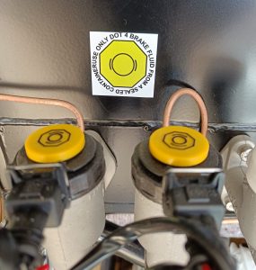
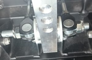
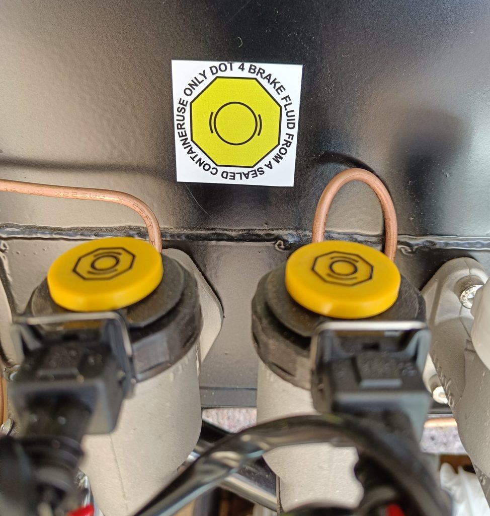
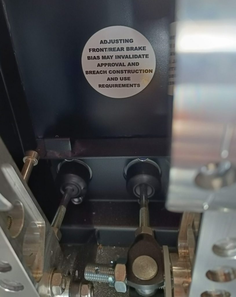
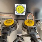
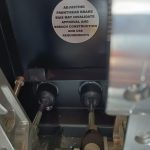
Brake cylinders, bias bar and IVA stickers.
A gentle start to the build, installed the IVA compliant brake fluid reservior caps, along with the DOT4 fluid only sticker. I also set up the brake balance bar to maximum front braking pressure and then used two castellated 7/16″ UNF nuts and cotterpins to fix the bias bar adjustment in that position, adding the IVA sticker too.


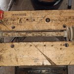
Fuel tank in and rear suspension started.
10th March, 2025
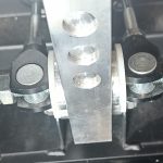
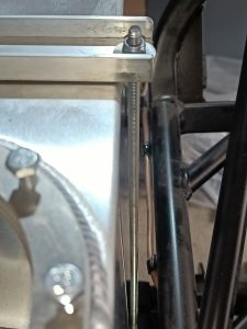
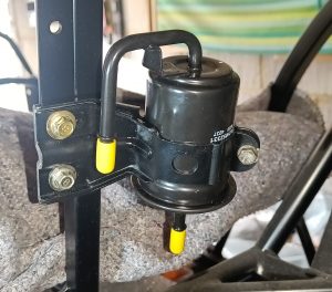
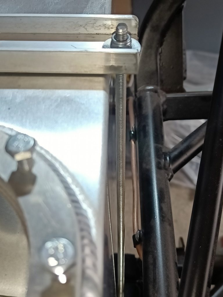
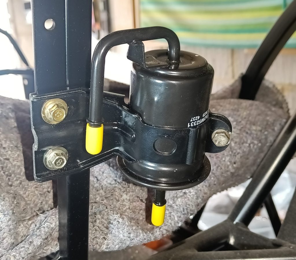
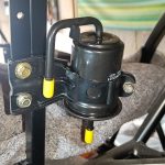
The fuel tank went in today, whilst waiting for the top coat of POR-15 on the diff nose & housing to dry. I did shorten the two supplied tank brackets as they seemed unduly long (echoing Colin Chapman’s philosphy of ‘building lightness’ into a car). I also took care to make sure that the threaded bars ran parallel to the tank sides with sufficient clearance all the way down (both the tank and the rear brake lines). Also fitted the fuel filter bracket and filter.
11th March, 2025
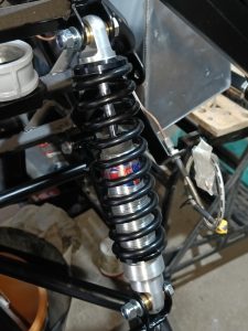
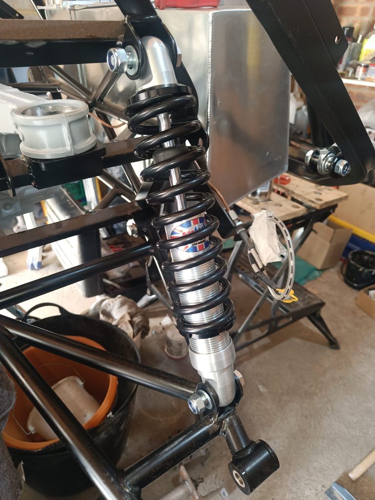
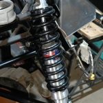
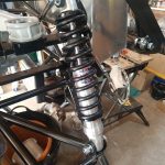
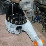
Whilst waiting for some parts to complete the fuel pump assembly modification, and to re-assemble the differential nose and housing, I started on fitting the rear suspension. The manual is excellent at explaining the process, nicely backed up with YouTube content from The Parrott Bros. The bushes and crush tubes pushed in very easily (using the workmate) and the bolt packs supplied meant it was easy to find the correct hardware to install the rear wishbones. Fitting the coil overs was a little more tricky as they were not supplied as a single unit – the spring needed to be compressed to fit on to the shocker (the 12 tonne press and very heavy duty cable ties solved the problem).


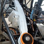
Two steps forward & one backward…
13th March, 2025
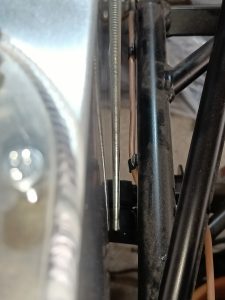
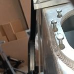
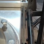
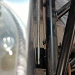
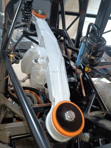
Something was nagging me about the rear shocker I’d fitted on the 11th March and rewatched The Parrott Bros video. I then realised that I’d used a 13″ Protech front suspension shock instead of the 14″ – the giveaway was the brass bushes are only on the front shocks. There’s nothing on the boxes to say which go where other than a hand written ‘R’ on one of the boxes (which I hadn’t previously noticed) and nothing in the manual either, as far as I could find. All of this explained why I needed to compress the spring to get it to fit, which was totally not necessary if you use the correct shock in the first place. Had to use a ratchet strap to recompress the shock whilst still fitted to the car in order to remove the spring once the shock was out. Can you spot the difference between the two image of the N/S rear shock installation in the gallery above…..?
I had also fitted 12mm crush tubes on the lower wishbone for the upright instead of the 14mm ones (which I now need to find). This only became apparent when I tried to fit the upright into the wishbone with the 14mm bolt supplied – it didn’t. In this case I should have read the manual more carefully!
14th & 15th March, 2025
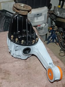
I located the errant 14mm bushings and crush tubes for the lower rear wishbone upright bolts, and fitted the uprights for good measure too.
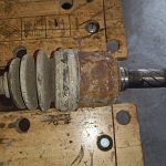
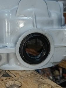
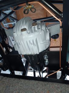
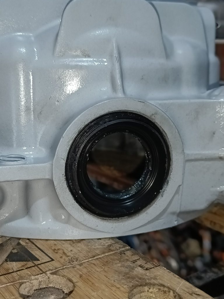
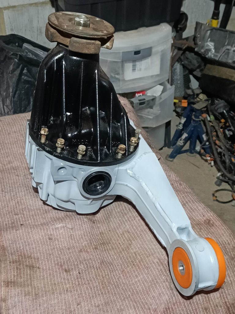
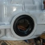
Time to fit the differential assembly into the chassis. To do so I had to fit the ‘nose’ back into the housing and replace all three oil seals. Pretty straightforward along with cleaning up the all of the original casing bolts. Used Blue Hylomar between the two main joint surfaces and torqued the bolts to 20 ft lbs. Then with some assistance from a neighbour put the complete unit into the chassis. I had to slightly elongate the two holes in the chassis plate for the M12 front diff bolts and the die grinder made short work of the extra 2-3mm required for the bolts to clear.
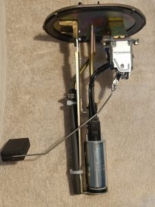
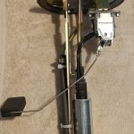
I also completed the fuel pump assembly modifications (wiring the new pump to the Mazda connector) and fitted this into the tank. A bit fiddly getting all eight bolts to line up with the boss on the tank as the rubber seal was determined to pull them awry and cross thread them! I tightened them as much as I dare, 6 or 7 ft lbs.


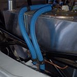
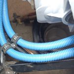
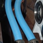
Flexi fuel lines fitted & more refurb.
16th – 31st March, 2025
General update for the last two weeks of March. Various family gatherings and DIY obligations meant that working on the MK has been a sporadic affair lately.
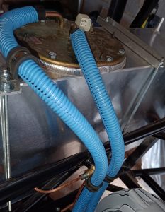
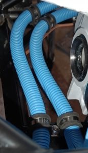
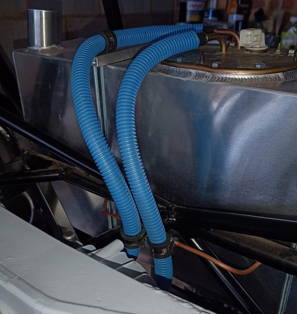
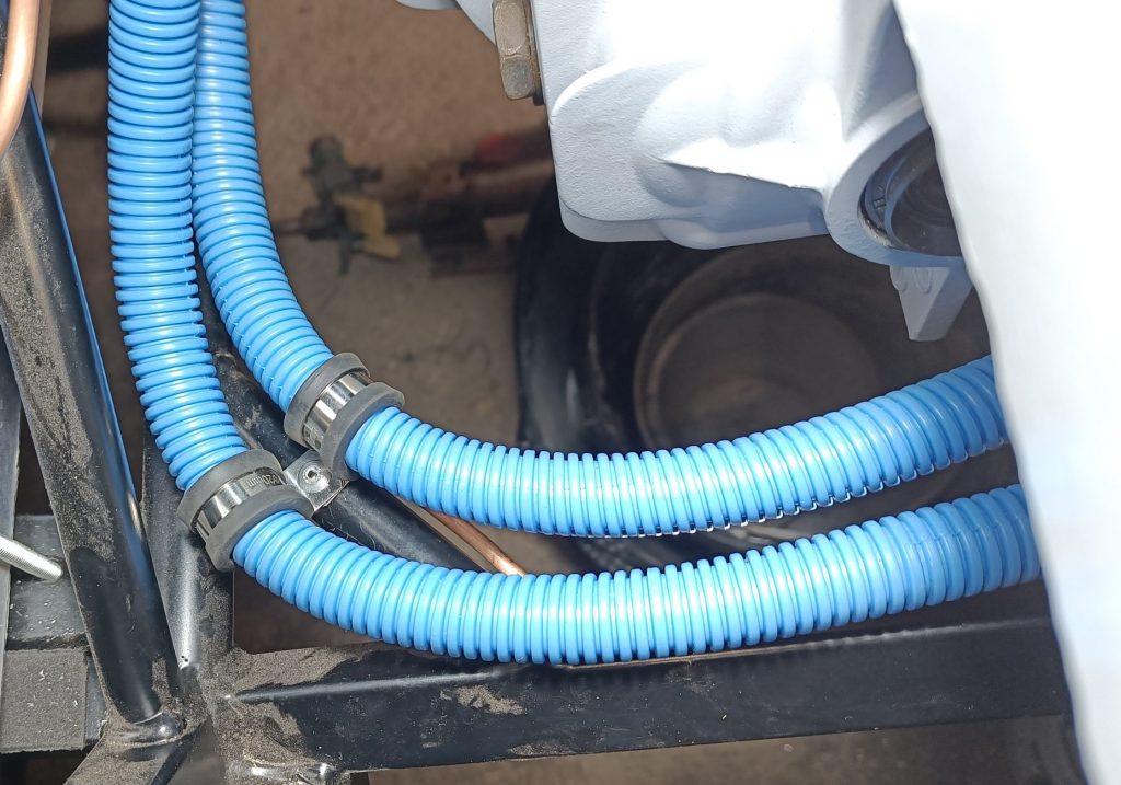
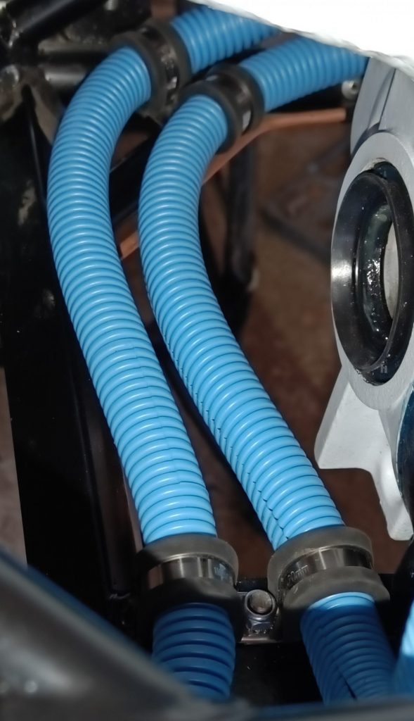
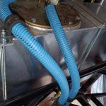
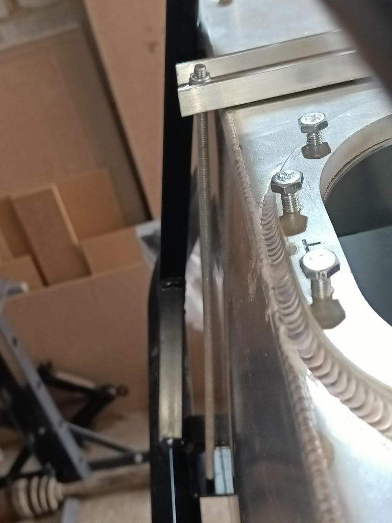
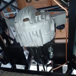
A fair amount of time was spent working out the best route for the flexi fuel lines from the tank to the rigid pipes as the latter had been fitted by MK using a newer single rubber ‘P’ clip approach (you can see this in this YouTube video from MK). This meant the both flow and return lines were best run over the O/S diff fixing plate rather than one over and one under, as shown in the manual. Seems to have worked out well! And I like to make the build look a little more appealing hence the blue convouted tube over the flexible fuel pipes, to tie in with the body work colour.
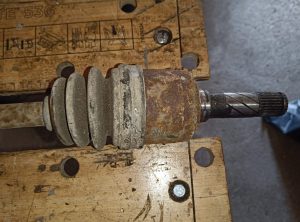
9th May update – Not completely happy with the clearance between the fuel lines and the O/S driveshaft inner CV joint boot, now that this has been fitted. Going to change the routing to that shown in this MK video. Link to new images here.
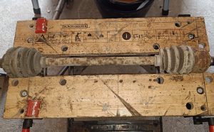
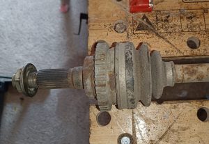
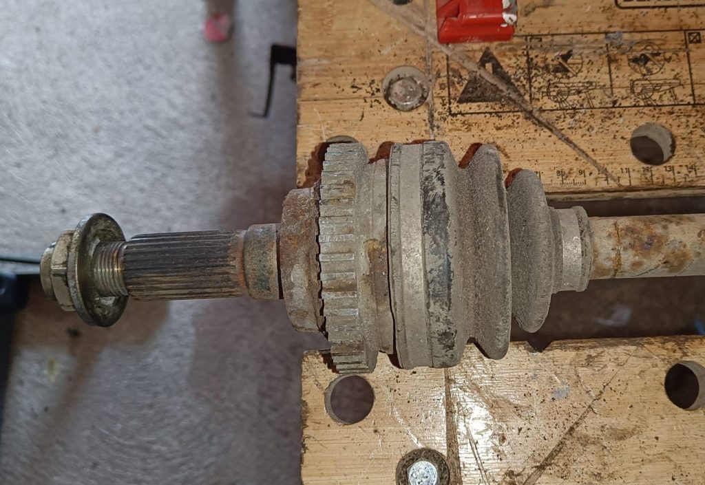
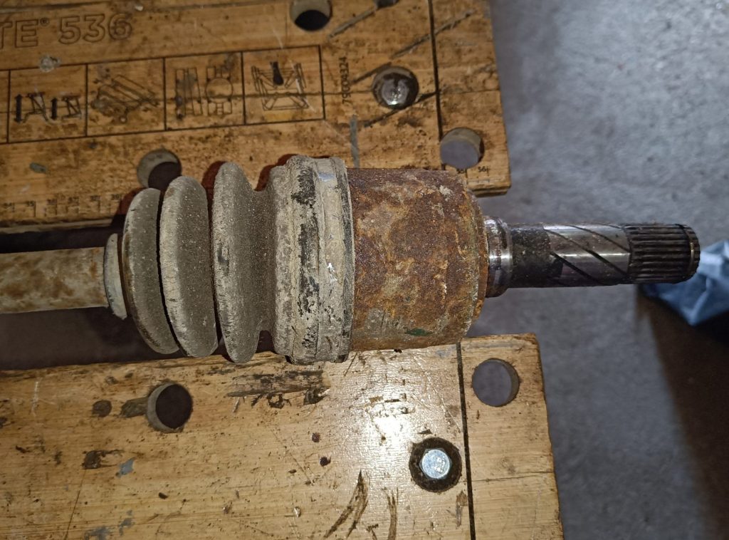
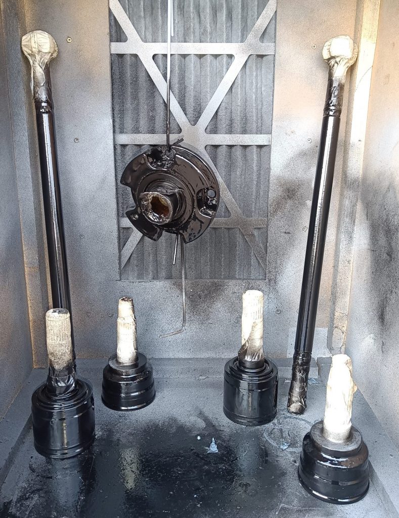
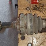
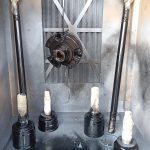
Otherwise time was spent on cleaning up and painting the propshaft, driveshafts and the diff input flange, ready to fit once I’ve fitted the wiring loom saddles. I also need to dry fit the interior panels before going too much further into the build.